
Flex Cut – FC500

Instruction how to use
To secure personal safety for the operating and maintenance personnel in their work with the FAS Converting equipment, all personnel should be instructed how to use the manual.
The manual is divided in three parts:
Part one
Contains safety instructions and information about responsibility. All personnel working with the machine should read and understand this part.
Part two
Contains instructions how to operate the machine. This part must be accessible to operating personnel.
Part three
Gives instructions regarding service, settings and adjustment. This part which isavailable only in English is addressed to maintenance personnel and forproduction/operating managers.
The machine is equipped with an Omron control panel. This panel has some features that is password protected. Operating personnel have access to all main functions and the password protected features is for maintenance personnel and production/operating managers only.
The machine is delivered with two complete manuals, part 1-3 stored on USB memorysticks.
Additional manuals or parts there of can be purchased from:
FAS Converting Machinery AB
Service department
Phone +46 10 405 05 00.
Email: service@fasconverting.se
#1 – Responsibility and Safety instructions
Responsibility
The Flexcut (FC500) is designed to cut handles or aprons from polyethylene film. All other utilization to cut other materials is prohibited unless permission has been given by FAS Converting Machinery AB.
FAS Converting Machinery AB will not be liable for damages or injuries caused by alterations done to the machinery.
FAS Converting Machinery AB is not responsible if the machinery is altered or not used according to the manufacturers instructions or specifications.
FAS Converting Machinery AB takes no responsibility if manuals not are made available to personnel concerned.
FAS Converting Machinery AB provides instruction manuals with every machine.
It is the customers responsibility to make this manual accessible to all personnel. It is the customers responsibility to thoroughly instruct the operators in how to safely run and maintain the FAS-machinery, thus avoiding undue injury.
Health and safety information
This document contains important hazard information. The hazard information is prioritized into Danger, Warning and Caution notices, all of which appear in this chapter. The appearance of a warning symbol elsewhere in this manual means that you must refer to the appropriate Danger or Warning notice in this chapter before proceeding. The warning symbol is:
Before attempting to operate the machine you must read this chapter and pay particular attention to all the Danger, Warning and Caution notices. Failure to do so could result in serious injury to personnel or damage to the equipment.
Before attempting to operate the machine you must read this chapter and pay particular attention to all the Danger, Warning and Caution notices. Failure to do so could result in serious injury to personnel or damage to the equipment.
All personnel who operate and service the machine must be well-trained on the equipment and familiar with its modes of operation.

Imediate danger to life!
Failure to observe this information will put your life in danger! Each DANGER NOTICE specifically states the nature of a particular hazard and the means by which it can be avoided. DANGER NOTICES are presented in the style of this notice.

Risk of serious personal injury!
Failure to observe this information could result in serious personal injury! Each WARNING NOTICE specifically states the nature of a particular hazard and the means by which it can be avoided. WARNING NOTICES are presented in the style of this notice.

Risk of minor personal injury or damage to equipment!
Failure to observe this information may result in minor personal injury, or could result in damage to equipment! Each Caution Notice specifically states the nature of a particular hazard and the means by which it can be avoided. Caution Notices are presented in the style of this notice.
Safety precautions
This machine operates from a mains electrical supply and therefore lethal voltages are present within the machine when it is switched on. All personnel must exercise extreme caution when in the vicinity of the machine when covers, panels or guards are removed.
The machine contains moving parts and risk of personal injury will be apparent when the machine guards are removed.
Adjustments to the machine must be performed by authorised personnel only, who must exercise extreme caution at all times.
All personnel in the vicinity of the machine must exercise extreme caution regarding clothes, gloves and long hair. All operators with long hair must under all circumstances wear hairnet. Operators should not wear gloves, or loose fitting clothes.
When handling plastic film static electricity may occur.
The dancer is moving vertically. Always keep hands away from the dancer while moving. If the web brakes the dancer will fall down in high speed. There is a risk of personal injury caused by crushing.
High voltage is present in the spark head area. Always keep hands away from this area when spark is set to “ON”. There is also a risk that the capacitor discharges when the machine is turned off.
Safety
For the safety of the operator, the machine is fitted with both fixed guards and guards that can be opened. The machine has 2 emergency stop buttons, see figure below for location.

Safety labels and switches
- CE-sign
- Warning sign
- High voltage
- Emergency stop
- Fixed guards
- Warning sign “Crush ganger”
- Warning sign “Warm”
When the machines in a line working are working in series, operating the emergency stop, opening or removing one of the openable guards on any of the machines in the line, will cause a complete shut down of the machines.
Fixed guards must under any circumstances not be removed from the machine while during production.
Safety-switches must not be tampered with to bypass the safety interlocks, making it possible to open the doors and guards while the machine is in production.
All broken or malfunctioning safety-switches must be replaced immediately.
Bypassing the safety switches
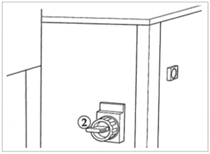
When performing settings and adjustments, the safety switches can be bypassed by setting the bypass turn-key to the hand position. The machine then operates without the clutch-brake. In order to operate the clutch-brake when the turn-key
is in hand position the two-hand control device must be used. At all times, other than when the machine is under service- or maintenance, the turn-key switch must be disengaged and the key removed.
Serviceing and maintenance work must always be performed by authorised personnel only, who must exercise extreme caution to avoid the risk of personal injury.
#2 – Operating manual
Installation
Place the Flexcut between and as close as possible to the Bag machine and Winder, in case of Apron Flex cut place the Flex cut as close to the Extruder as possible. The distance between the fan outlet and any possible pipe elbow shall be at least 2 m.
Refer to figure below.
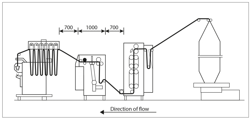
Do not secure the Flex cut in any way. Instead place it directly on the floor where it can be mowed and is easily accessible for servicing. The machine is fitted with wheels that run on rails, this makes it possible to adjust the machine laterally.
Refer to Settings and adjustments.
Electrical and compressed air supply connections are provided at the lower part of the machine. For ease of maintenance the electrical cables and air tubes can be suspended from the ceiling and attached with quick connectors.
Power supply, standard: 400-480 V 50-60 Hz, Neutral and Earth
Fuse rating: 16 A
Compressed air: 6 bar (required pressure)
Consumption: Max 200 litres per minute
Interlocking
The machine can be interlocked to ensure that all machines in the production line stop automatically in the event of a fault in any one machine. The interlocking cable is ordered separately. If interlocking is not used, a special connector must be fitted to the interlock surquit for the machine to run.
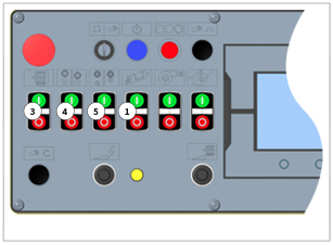
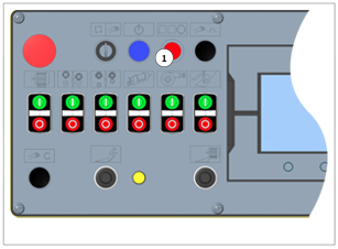
The operating panel
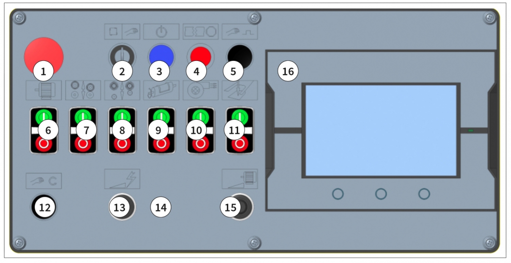
- Emergency stop
- Safety Bypass turnkey
- Reset Supply
- Auto stop
- Manual start Pulse/Two hand control device
- Main motor On/Off
- Nip Open/Close
- Brush roller Open/Close
- Cutter On/Off
- Fan On/Off
- Pusher On/Off
- Manual start Pulse/Two hand control device
- Spark intensity potentiometer
- Spark indication LED
- Machine speed potentiometer
- Control panel
Using the touch control panel
The control panel is a modern touch panel where buttons shown on the display are simply pushed in order to send a command. There is a main menu shown in default and various submenus can be selected simply by pushing the screen area where the button or field is shown. If a button is pressed a command is sent and corresponding action is taken. If a numeric or alphabetic field that is white is pressed a keypad will be shown on the display in order to key in figures. Fields in grey are read only fields
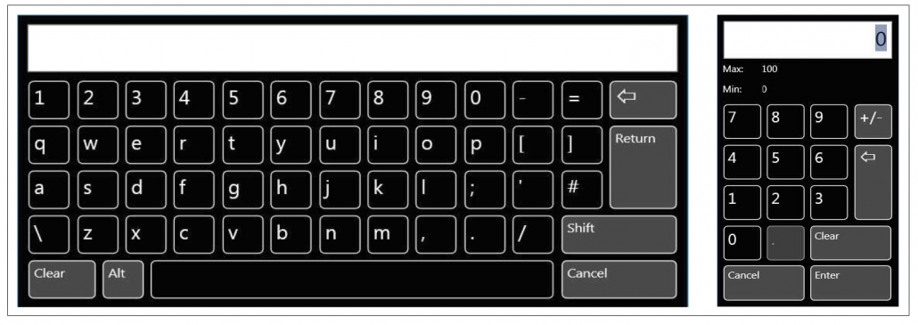
Entering text and figures with keypad
Whenever a field is pressed where text or figures shall be entered or changed, a pop up keypad will be shown. Press on the figures (or characters) as needed and when done confirm the setting by pressing the Enter key.
Press Cancel in order to close the keypad without saving any changes.
Press Clear to clear all figures in the field.
The control panel menus
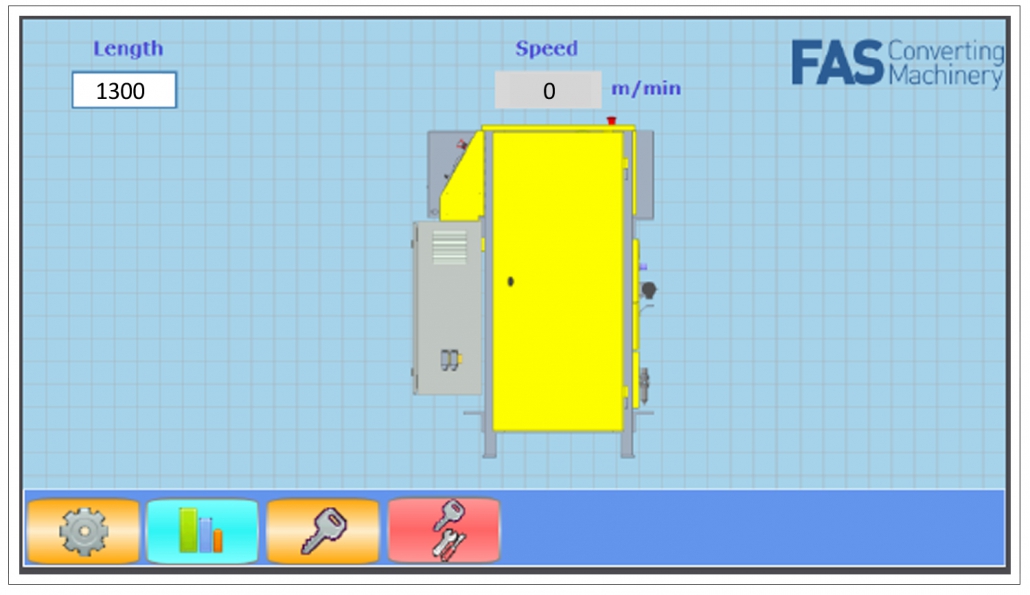
Main Menu
![]() The main menu will be shown as standard on power up. You can always go back to the Main menu by pressing key from any other menu
The main menu will be shown as standard on power up. You can always go back to the Main menu by pressing key from any other menu
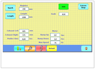
In the main menu the Apron/Bag length can be seen or set and the machine speed (m/min)
Editable fields in the Main menu
Length
Press the white field in order to bring up the keypad for entering the desired length. In spark mode this field is not active.
![]() Settings
Settings
Press this button to select the Settings menu. See “ Settings menu” below.
Settings menu

![]() Spark mode On/Off
Spark mode On/Off
Used when running T-shirt bags or S-Cut
![]() Length mode On/Off
Length mode On/Off
Used when running Aprons.
![]() Choose between metric or inch mode
Choose between metric or inch mode
![]() External stop On/Off
External stop On/Off
Used when using interlink cables between machines.
Register
Press the white field in order to bring up the keypad for changing the register. When running in spark mode, the cut position can be adjusted compared to the perforation.
Length
Press the white field in order to bring up the keypad for changing the length. Exhaust Right, Exhaust Left: Press the white field in order to bring up the keypad for changing the Exhaust timing, relative to the centre of the cutter.
Pusher time
Press the white field in order to bring up the keypad for changing the Pusher time. ( normally 0,02 – 0,04 Sec )
Scale
Press the white field in order to bring up the keypad for changing the Scale factor. The scale factor is used for conversion from impulses to actual length. If the set length does not correspond to the produced Bag/Apron the Scale factor needs to be adjusted. (Standard setting is 8,92 impulses/mm )
Ramp up, Ramp down and max speed
Press the white field in order to bring up the keypad for changing Ramp Up/Down and max speed.
Statistics menu
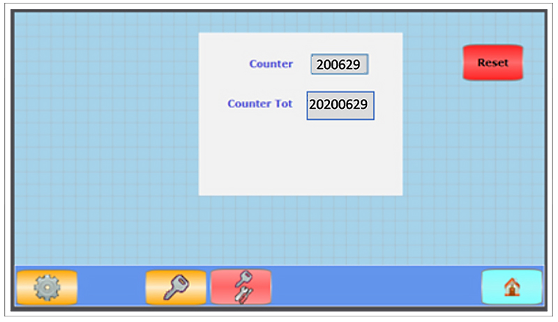
![]() Press this button to bring up the statistics menu. Here the total number of cuts for machine can be seen, also the number of cuts since last reset. Number of cuts since last reset is very useful in order to know how many cuts the actual mounted cutter have done.
Press this button to bring up the statistics menu. Here the total number of cuts for machine can be seen, also the number of cuts since last reset. Number of cuts since last reset is very useful in order to know how many cuts the actual mounted cutter have done.
![]() By pushing button the counter goes to zero.
By pushing button the counter goes to zero.
Note You must be logged in at least to level 1 to be able to reset the counter
![]() Press this button to bring up the log in field.
Press this button to bring up the log in field.
Use Level 1 ( L1 ) or Level 2 ( L2 ) as Log in name.
Note Password for Level 1 and 2 is provided to the Factory management.

Fill in L1 or L2 for suitable log in level

Fill in suitable password for the desired login level.

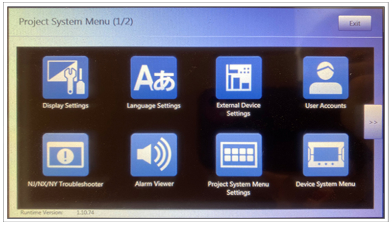
![]() Press this button to bring up the HMI system meny.
Press this button to bring up the HMI system meny.
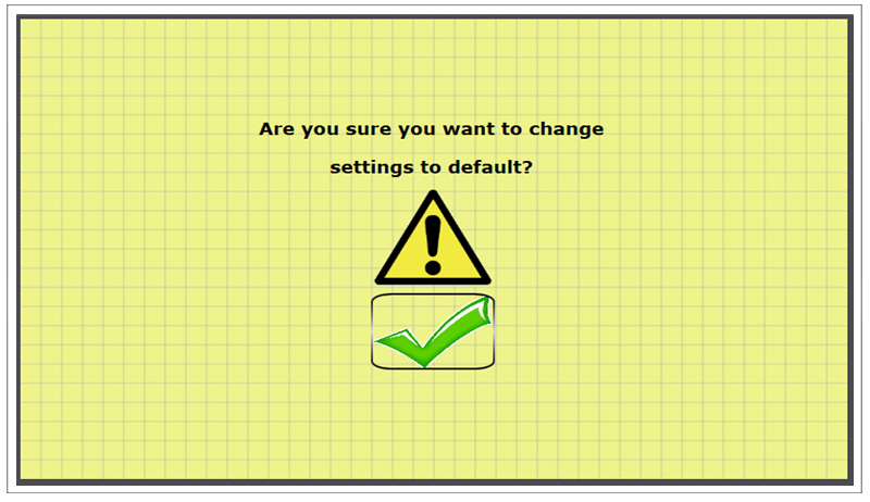
![]() Press this button to select default values. This is usable when setting up a new machine. If the selection Default is not used the parameters has to be entered in various menus.
Press this button to select default values. This is usable when setting up a new machine. If the selection Default is not used the parameters has to be entered in various menus.
Starting and operation
Before starting
NOTE that if the machine is shut off by means of the emergency stop button, for example, and the cutting tool is not in an upward position, the cutting tool must be manually turned to the upper position before starting.
1. Make sure the cutting tool is in the upper position. Follow the description below:
The cutting tool is very sharp, which means that there is a risk of injury caused by cuts.
Flexcut with bolted cutting tool
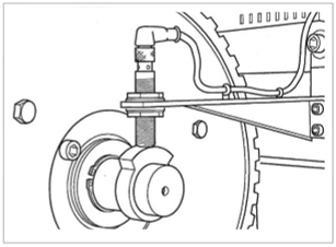
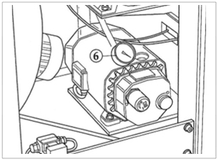
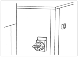
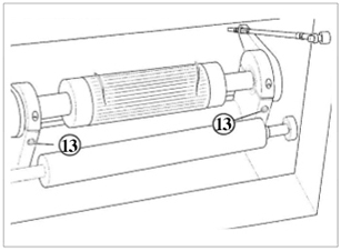
To safeguard the cutting, the tool shaft is fitted with a brake facility that is activated when the main switch is disengaged, see fig 1.
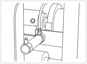
Figure 1
Carefully turn the cutting tool by hand until the cutting area is in the upper position, see fig. 2.
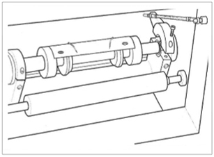
Flexcut with fixed cutting tool
To sense the upper position an inductive sensor is fitted that is activated by a cam so that the sensor connects the current supply to the motor only when the cutting area is in the upper position, see fig 2.
Open the side door and rotate the cutting tool by hand until the cutting area is in the upper position.
Close the door
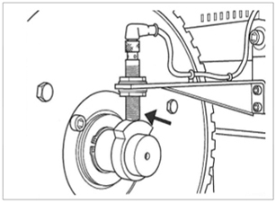
Figure 2
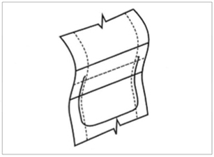
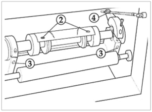
When producing T-shirt bags, gusseted web shall be used. The web shall have two seals ( 1 ), with perforation (2) in between. Refer to fig. 3.
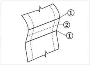
Figure 3
The perforation shall be weaker in the middle and stronger at the edges.
2. Set the safety bypass turn key to auto position and remove it.
3. Place the spark sensor which is attached to a cylinder, opposite to the square spark shaft.
4. Place the spark sensor at a distance of 2-4 mm from the spark shaft.
Note It is important to keep the spark sensor clean.
5. Set the pressure for the nip roller at 3 bar.
Starting
1. Check to make sure that the cutting area on the cutting tool is in the upper position, see fig 2 in “Starting and Operation“.
2. Set the main switch to ON position.
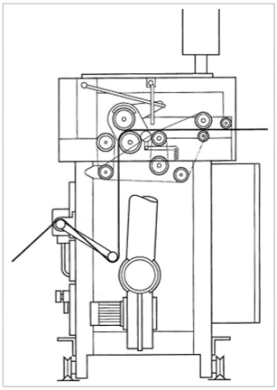
3. Thread the web through the Flexcut as shown.
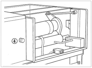
4. To feed the web inside the Flexcut, press the green button on the rear side of the machine. The web is blown between the anvil roller and the cutting tool when the green button is pressed.
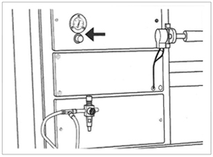
5. Press RESET. The vacuum pump starts to operate.

6. Check to make sure that the vacuum pump’s pressure is set at – 0.7 bar.
7. Set the machine speed potentiometer to position 0
8. In turn set the MAIN MOTOR, NIP, and BRUS ROLLER buttons to ON. The indicator LED for each button illuminates.
9. Take up the slack web from the extruder or bag machine by carefully increasing the speed potentiometer to 100%
10. Feed the web to the winder.
11. Make sure the web does not slack between the Flexcut and the winder.
12. Set the cutter to ON. The indicator LED illuminates.
13. Adjust the SPARK POWER to a suitable intensity ( normally setting 5 ), i.e. until there is a steady spark for every perforation. If running in LENGTH mode the spark is not used.
14. Activate the FAN and PUSHER buttons to start the fan and pusher function. The indicator LED for each button illuminates.
Check the cut position and if necessary adjust the REGISTER setting in the settings menu, see “Register“.
If running in LENGTH mode the register value is not used.
Correct cutting position
Shutting down
Planned shut down
1. Stop the cutter by pushing the cutter stop button, The indicator LED Fan and Pusher stops automatically.
2. Set the MACHINE SPEED potentiometer to 0
3. Stop the MAIN MOTOR by pushing the main motor stop Theindicator LED distinguishes.
4. Open the nip roller by pushing the nip open button.The indicator LED
5. Open the brush nip roller by pushing the brush roller open Theindicator LED distinguishes.
6. Set the main switch to OFF
Emergency shutdown
When any of the emergency stop buttons are pushed, the movable parts of the machinecease to function.
In case of emergency shut down the cutting tool must be manually turned to the upperposition before the machine can be started.
Automatic shutdown
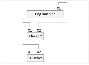
The Flexcut can be interlocked to enable all machines in the production line to stop if anyfault should arise in one of the machines ( e.g. the dancer in the Flexcut or Winder dropsdown ) see connection below.
1. To enable an automatic shutdown, press AUTOSTOP on the operating panel.
Single web production
Double web production
#3 Settings and adjustment & Service
Settings and adjustments
Adjustments during operation.
Setting of cut out position: By changing the Register value the cut out position relative to the perforation will be changed.
Setting of Length
By changing the length value the distance between cuts can be adjusted.
Cutter pressure
The cutter pressure can be adjusted during operation by operating the turn key, the cutter will then stop and the out feed cover can be opened and the cutter adjusted. Close the cover and turn back the key in order to go back in production.
Lateral setting of machine
Lateral adjustment of the cut position can be made by moving the machine with the crank handle.
Other settings
Belt tensioning
The drive belts are correctly tensioned when they can be pushed down between the pulleys by about 10mm. Readjust the belt tension by loosening the centre screw and moving the bearing housing.
Note! Excessive belt tension will damage the bearings.
Checking the vacuum pump’s working pressure.
The vacuum pump supplies a vacuum to operate the clutch/brake. The working vacuum shall be – 0,7 bar. Adjust the pressure by means of the black adjusting knob, if so required. Clean the filter once a month.
Clutch/Brake
Check the ventilation filters on the electromagnetic valves regularly to ensure that they have not become clogged and that the bearings are not damaged.
Cutting tool replacement
Cutting toll replacement may be performed by authorized personnel only. If the cutting tool is set incorrectly it will become damaged very quickly.
Take caution when working with the cutting tool as it is very sharp.
Note! Make sure not to damage the edges when replacing the cutting tool
Flexcut with bolted cutting tool
1. Set the main switch to OFF position
2. Turn the cutting tool to the upper position Unscrew six attaching screws from the cutting shaft and remove the cutting tool.
3. Loosen the two eccentric bearing’s lock screws a few turns.
4. Loosen the lock nuts and adjusting nuts on the eccentric setting device a few turns.
5. Place the new cutting tool into position, and make sure that it is turned correctly. Fit the six attaching screws.
Tighten the screws.
Make sure that the new cutting tool is not too low before proceeding, check the function by rotating the cutting tool by hand
6. Start the machine and feed the web into the machine. Follow the procedures described in section Starting, steps 1-9.
7. Press MANUAL PULSE button to rotate the cutting tool one full turn.
8. Tighten the adjusting nuts 1/6 turn, and run the cutting tool one full turn. Repeat this operation until the cutting tool cuts satisfactorily in both ends.
9. Tighten the eccentric lock screws and re- check the cutting tool function. Tighten the adjusting nuts slightly if so required. Tighten the lock nuts.
The cutting tool may raise slightly when lock nuts are tightened, therefore re- adjustment may be necessary.
Note! It is essential that the cutting tool pressure is even on the anvil roll to reduce wear. Make sure to adjust the adjusting nuts not more than 1/6 turn each time, and adjust each end individually. Do not let the cutting tool apply more pressure than necessary to the anvil roll to reduce wear.
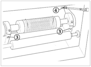
Flexcut with fixed cutting tool
1. Set the main switch to OFF position
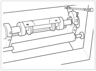
2. Loosen the six allen screws on the flexi- coupling ( three at each end ) and remove the flexi-coupling.
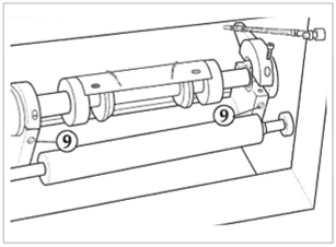
3. Loosen the two eccentric bearing’s lock screws a few turns.
4. Loosen ( and remove ) the lock nuts, adjusting nuts, washers and rod on the eccentric setting.
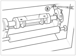
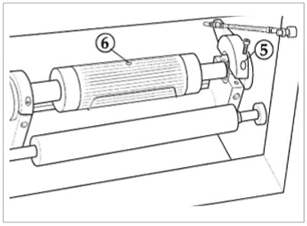
5. Loosen and remove the two bearing caps.
Note! Make sure that the bearing caps are mounted back at the same position.
6. Turn the cutting tool so that the lift-hole is accessible. Mount the eye bolt and carefully lift the cutting tool using a crane.
Note! The red eye bolt should be mounted on the frame during transport but when the machine is installed it should be placed on the hook near the cutting tool.
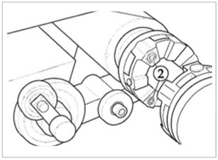
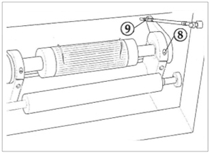
7. Move the drive coupling to the new cutting tool
8. Mount and fasten the two bearing caps. Tighten the screws.
9. Re-assemble the eccentric setting device. Re-assemble the flexi couplings. Tighten the nuts by hand, make sure the cutting edge is not touching the anvil, check the function by rotating the cutting tool by hand.
10. Start the machine and feed the web into the machine. Follow the procedures described in section Starting, steps 1-9.
11. Press MANUAL PULSE button to rotate the cutting tool one full turn.
12. Tighten the adjusting nuts 1/6 turn, and run the cutting tool one full turn. Repeat this operation until the cutting tool cuts satisfactorily all the way.
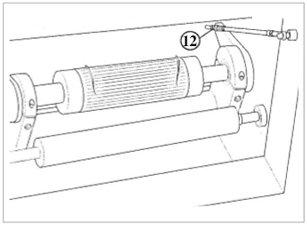
13. Tighten the eccentric lock screws and re- check the cutting tool function. Tighten the adjusting nuts slightly if so required. Tighten the lock nuts. The cutting tool may raise slightly when lock nuts are tightened, therefore re- adjustment may be necessary.
Note! It is essential that the cutting tool pressure is even on the anvil roll to reduce wear. Make sure to adjust the adjusting nuts not more than 1/6 turn each time, and adjust each end individually. Do not let the cutting tool apply more pressure than necessary to the anvil roll to reduce wear.
FAS Converting (FAS Converting Machinery AB and FAS Converting Machinery Inc) can accept no responsibility for possible errors in catalogues, brochures and other printed/digital material. All trademarks in this material are the property of the respective companies. FAS Converting and the FAS Converting logotype are trademarks of FAS Converting Machinery AB. All rights reserved.